How to tell if a refrigerator's NTC sensor is damaged: tests with a multimeter
Is your refrigerator over-cooling, not freezing properly, or keeping the compressor running for hours without turning off? Before you assume the problem is with
Is your refrigerator over-cooling, not freezing properly, or keeping the compressor running for hours without turning off? Before assuming the problem lies with the electronic control board or the motor, it's worth checking the temperature sensor.
To determine if a refrigerator's NTC sensor is faulty, you must measure its resistance with a multimeter and observe how it changes when you cool or heat it. In a functioning NTC sensor, the resistance increases when the temperature decreases and decreases when it rises.
However, there's something many people overlook: not all NTC sensors have the same values. A 5 kΩ sensor doesn't measure the same as a 10 kΩ sensor, and a seemingly unusual reading doesn't necessarily mean it's faulty.
In this guide you will learn how to identify symptoms, locate the sensor, perform tests correctly, and interpret the results to avoid unnecessary part replacements.
What is an NTC sensor and what is it used for in a refrigerator?
An NTC sensor is an electronic component that allows temperature to be measured through changes in its electrical resistance.
The acronym NTC comes from the English Negative Temperature Coefficient , which means negative temperature coefficient.
Its operating principle is simple:
- When the temperature decreases, the sensor's resistance increases.
- When the temperature increases, the resistance decreases.
The electronic board uses these changes to interpret the temperature at different points in the refrigerator.
For example, if the preservation compartment starts to heat up, the sensor modifies its resistance and the board can use that information to control the cooling system.
When the programmed temperature is reached, the electronics adjust the operation of the equipment according to its design.
No Frost refrigerators may also have sensors responsible for monitoring the evaporator temperature and participating in the control of automatic defrosting.
Therefore, a sensor that provides incorrect information can disrupt the operation of the refrigerator, even if the compressor and other components are in good condition.
What symptoms does a refrigerator with a damaged NTC sensor exhibit?
A faulty NTC sensor can produce different failures depending on its location and how the electronic board uses its readings.
The most common symptoms include the following.
1. The refrigerator is getting too cold and freezing the food.
If the sensor reports a higher temperature than the actual temperature, the card may maintain cooling for longer than necessary.
As a result, vegetables, drinks, and other foods could freeze inside the refrigerator compartment.
2. The refrigerator is not cooling enough
The opposite can also happen.
If the sensor indicates a lower temperature than the actual temperature, the control system could reduce the compressor's operation before reaching the required cooling level.
This can cause food to remain lukewarm or the freezer to not reach the programmed temperature.
3. The compressor runs for too long
When the temperature reported by the sensor is incorrect, the board may receive information that prevents it from properly regulating the operating cycles.
However, a compressor that is running continuously does not in itself confirm that the sensor is damaged.
Other possible causes include a poorly sealed door, high ambient temperatures, ventilation problems, or failures in the refrigeration circuit.
4. Error codes appear on the screen
Some digital refrigerators can detect sensors that are open, shorted, or outside of expected parameters.
When this happens, they display error codes or trigger an alarm.
The codes vary depending on the make and model. It is important to consult the relevant manual before associating a code with the NTC sensor.
5. Too much ice accumulates on the evaporator
In No Frost refrigerators, some sensors are involved in the defrosting process.
If the card receives incorrect information about the evaporator temperature, the defrosting process may be affected.
This could contribute to a buildup of frost that ends up blocking the circulation of cold air.
However, before blaming the sensor, the defrost heater, the thermal fuse, and the other system components should also be checked.
If your refrigerator exhibits this symptom, you can also consult our guide on how many ohms the defrost heater of a refrigerator should measure .
Where is the NTC sensor located on a refrigerator?
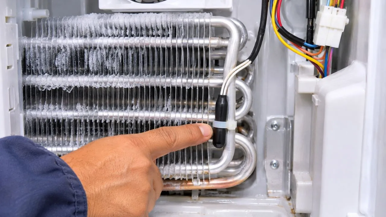
The location depends on the manufacturer, model, and function of the sensor.
Some refrigerators have only one temperature sensor, while others incorporate several to monitor different zones.
The usual places are:
Cooling compartment sensor: may be found behind a small plastic cover, on an interior wall, or integrated into an air circulation duct.
Freezer sensor: used to monitor the temperature of the freezer compartment.
Evaporator sensor: It is usually located near the evaporator pipes or fins, behind an internal panel of the freezer.
In certain models, there may also be additional sensors to control other functions.
Before removing any cover, identify the refrigerator model and consult its technical documentation.
It's important not to confuse an NTC sensor with a mechanical thermostat, a thermal fuse, or a defrost bimetal. Although they are all related to temperature, they function differently.
How to test a refrigerator's NTC sensor with a multimeter, step by step
This is the most important part of the diagnosis.
The test consists of measuring the sensor's resistance at a known temperature and checking if its behavior matches the expected behavior.
Step 1. Unplug the refrigerator from the power outlet
Before removing connectors or taking resistance measurements, completely disconnect the refrigerator.
Never set the multimeter to the ohms function while the circuit is energized.
This can cause damage to the instrument, the electronic board, or even an electric shock.
If the sensor is connected to an inverter board or electronic module, follow the waiting times and procedures specified by the manufacturer. Some circuits may retain energy after the equipment is disconnected.
Step 2. Locate the temperature sensor
Identify the sensor you need to check.
You will usually find a small probe with two wires connected to the electronic board or a harness.
In some devices the sensor is protected by a plastic capsule, while in others it may have an encapsulated tip.
Do not cut the cables to perform the test if you can access the original connector.
When the sensor is located behind the evaporator panel, remove the cover only by following the appropriate procedure.
Do not use pointed tools to detach sensors or remove ice near the cooling system pipes.
Step 3. Disconnect the sensor from the electronic board
This step is essential to obtain a reliable reading.
If you measure the sensor while it remains connected to the board, other circuit components may alter the value shown by the multimeter.
It is recommended to disconnect its connector and measure directly between the two terminals corresponding to the sensor.
If the measurement is taken from the circuit board harness, you must first identify the correct pins using the refrigerator's electrical diagram.
Don't rely solely on the color of the cables, as they can vary between models.
Step 4. Set the multimeter to measure resistance
Select the resistance function, identified by the symbol Ω.
If you are using a multimeter with a manual scale, select a range that allows you to measure the expected value.
For example, to check a 10 kΩ sensor at room temperature, you could use the 20 kΩ scale.
However, if you cool that same sensor, its resistance could exceed 20 kΩ and you will have to select a higher scale.
In auto-ranging multimeters, it is usually enough to select the resistance function.
Step 5. Place the multimeter probes on the sensor terminals
With the sensor disconnected, place one probe of the multimeter on each terminal.
In a conventional two-wire NTC sensor, the polarity of the probes does not matter when measuring resistance.
Wait a few seconds until you get a stable reading.
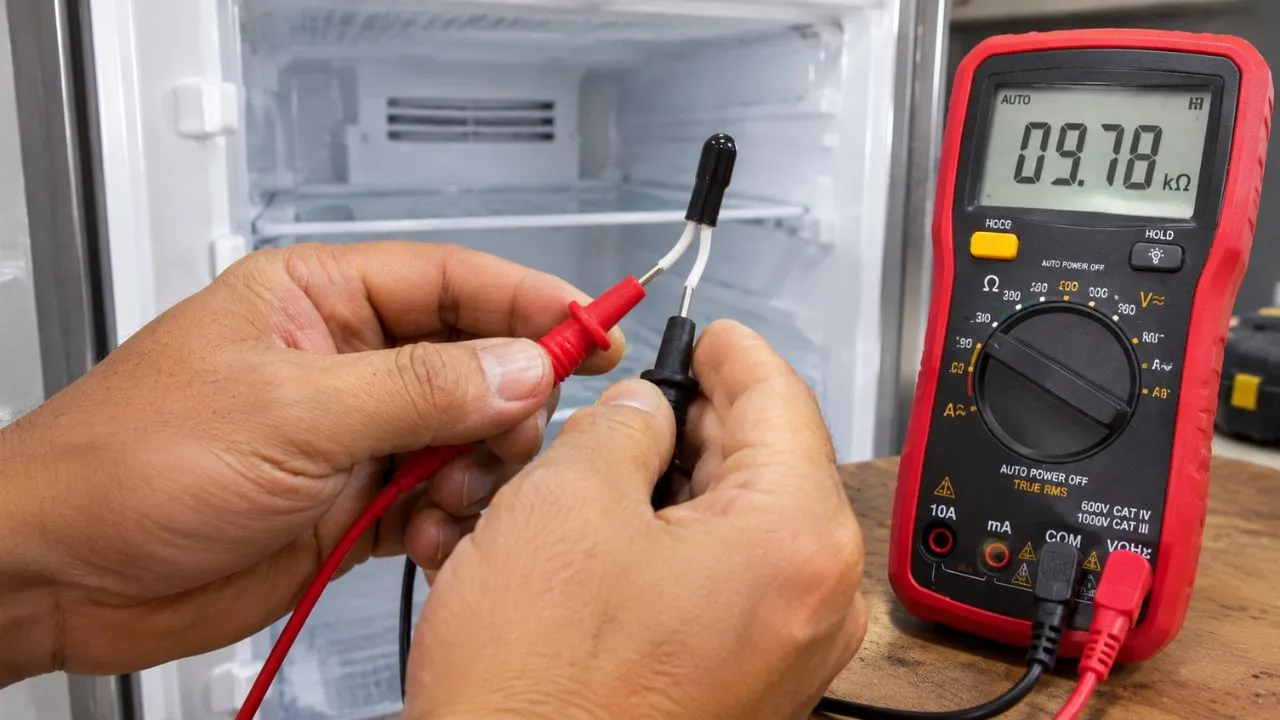
For example, the multimeter might display:
9.8 kΩ at a temperature close to 25 °C.
This reading could be compatible with a nominal 10 kΩ sensor, depending on its tolerance and resistance curve.
But you shouldn't conclude that any sensor that reads 9.8 kΩ is working correctly.
First you need to know what resistance that component should present at the test temperature.
Step 6. Check how the resistance changes with temperature
Once the initial measurement has been carried out, the test that allows the sensor's behavior to be checked comes next.
Cool the probe and observe if its resistance begins to increase.
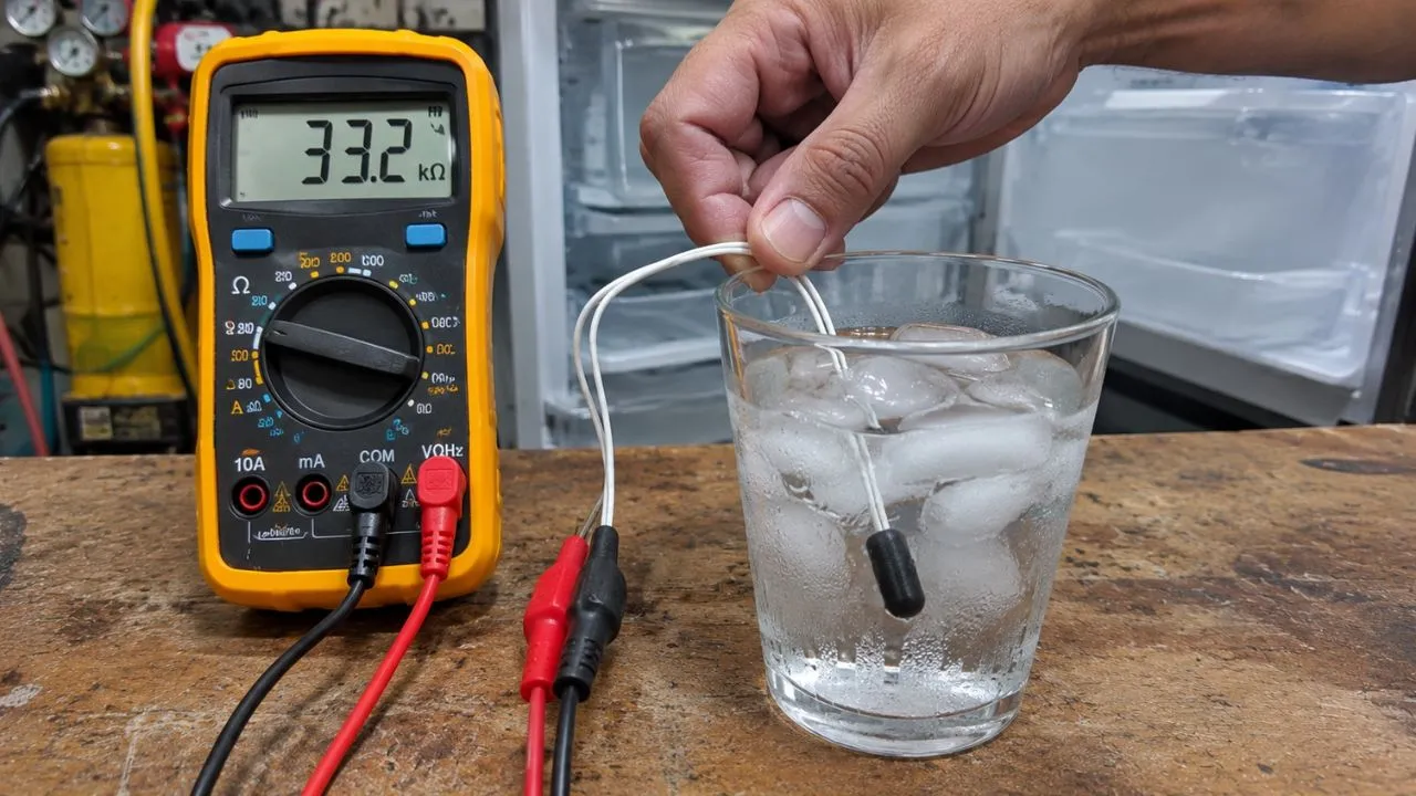
Next, allow it to return to room temperature and check if the resistance decreases.
A normal NTC sensor should show an inverse relationship between temperature and resistance.
If the sensor remains practically at the same value after a sufficient thermal change, exhibits interruptions, or shows unstable readings without explanation, there may be a fault.
Please note that this test checks your response, but does not by itself guarantee that your calibration is correct.
To complete the diagnosis, you must compare the resistance with the table corresponding to the model.
What resistance should an NTC sensor in a refrigerator read?
This is one of the most frequently asked questions when repairing digital refrigerators.
The answer depends on the type of thermistor used.
There are sensors with different nominal resistances, for example:
- 2.7 kΩ NTC.
- 5 kΩ NTC.
- 10 kΩ NTC.
There are other values as well, so you shouldn't assume that all refrigerators use one of these three.
Generally, when a sensor is identified as a 10 kΩ NTC, it means that its nominal resistance is 10,000 ohms at 25 °C.
That doesn't mean it will read 10,000 ohms at any temperature.
Reference table of resistance of NTC sensors
To understand the difference, look at this example of nominal sensors of 5 kΩ and 10 kΩ, both with a Beta coefficient of 3950 K.
| Temperature | NTC 5 kΩ | NTC 10 kΩ |
|---|---|---|
| 0 °C | 16.8 kΩ | 33.6 kΩ |
| 10 °C | 10.1 kΩ | 20.2 kΩ |
| 20 °C | 6.3 kΩ | 12.5 kΩ |
| 25 °C | 5.0 kΩ | 10.0 kΩ |
| 30 °C | 4.0 kΩ | 8.0 kΩ |
Important: This table is an approximate mathematical example calculated for sensors with a Beta of 3950 K. It does not represent a universal refrigerator table nor does it replace the manufacturer's values.
Two sensors with the same resistance at 25 °C may exhibit different resistances at other temperatures if their Beta curves do not match.
Therefore, to confirm if a sensor is correctly calibrated, you need to know its nominal resistance, its characteristic curve, and the acceptable tolerance.
How to test the NTC sensor with water and ice
A practical way to test a thermistor is to use a mixture of water and ice.
This test allows for a reference temperature close to 0 °C, provided there is enough ice in contact with the water and thermal equilibrium is reached.
Procedure
- Place clean water and plenty of ice in a container.
- Mix gently and allow the temperature to stabilize.
- With the refrigerator unplugged and the sensor isolated from the board, connect the multimeter to its terminals.
- Insert only the measuring tip if it is designed to be submerged and its encapsulation is intact.
- Keep electrical connectors and connections dry.
- Wait until the resistance reading stabilizes.
- Compare the result with the sensor's technical specifications.
If you are unsure whether the probe is waterproof, use a cooling method that does not wet it, such as a suitable sealed bag, verifying the actual temperature reached.
Practical example
Imagine you are checking a 10 kΩ NTC sensor at 25 °C, with a Beta curve of 3950 K.
At room temperature it could measure approximately 10 kΩ.
After cooling it to near 0 °C, its resistance should increase to approximately 33.6 kΩ.
If you observe that behavior, it's a good sign.
But you still need to check that the values are within the specified tolerance for that sensor.
If you use a different type of NTC sensor, the results will be different.
Don't confuse high resistance due to low temperature with a sensor failure.
How to interpret multimeter readings
When measuring an NTC sensor, you may find different results.
This table allows you to identify what each reading means.
| Multimeter reading | What could it mean? |
|---|---|
| Resistance increases upon cooling | Expected behavior of an NTC |
| Resistance decreases when heated | Expected behavior of an NTC |
OL or open circuit | Sensor, cable, or open connection; it could also be insufficient scale |
| Resistance close to 0 Ω | Possible short circuit |
| Reading that jumps when moving the cable | Possible intermittent connection |
| Stable resistance, but out of specification | Possible sensor is out of calibration or incompatible |
| Correct reading at two known temperatures | Indication of proper functioning |
What does OL mean on the multimeter?
It usually indicates a condition outside the measurement range or an open circuit.
But we must be careful.
If you are using the 20 kΩ scale and the sensor has a resistance of 30 kΩ, the multimeter might display OL even though the sensor is perfectly fine.
Before considering it damaged, switch to a higher scale.
What happens if the sensor reads zero ohms?
A reading very close to zero may indicate a short circuit in the sensor or its wiring.
However, verify that you are measuring the correct terminals and that the instrument is functioning properly.
What if the sensor's resistance changes, but the refrigerator continues to malfunction?
A sensor can respond to temperature changes and still display values outside its specified curve.
It may also be in good condition and there may be a fault in the wiring, connector or electronic board.
That's why it's advisable to take measurements at more than one known temperature, not just check that the multimeter reading changes.
How to distinguish a damaged NTC sensor from a fault in the electronic board
A fault in the control board can produce symptoms similar to those of a defective sensor.
To differentiate them, an orderly diagnosis must be followed.
First, check the sensor is disconnected from the electronic board.
If its resistance matches the expected curve at different temperatures, the next step is to inspect the cables and connectors.
Check especially:
- Rusty terminals.
- Moisture inside the connectors.
- Cut or crushed cables.
- Loose connections.
- Changes in resistance when gently moving the wiring.
If the sensor is working correctly and the wiring is in good condition, it may be necessary to check the electronic circuit responsible for interpreting the signal.
Voltage checks on a energized board should be performed by trained technicians, following the service manual. Attempting to measure unknown terminals is not recommended.
To guide the diagnosis based on your refrigerator's symptoms, you can use our diagnostic tool for digital and analog refrigerators .
Can a 5K NTC sensor be replaced with a 10K one?
Replacing a 5 kΩ NTC sensor with a 10 kΩ NTC sensor is not recommended simply because they both have two wires or are physically similar.
The electronic board interprets the temperature according to the resistance curve it expects to receive.
If you install a sensor with different characteristics, the board may interpret an incorrect temperature.
This could cause the compressor to run longer than necessary, the unit to cool less, or temperature errors to appear.
Even when two sensors have the same nominal resistance, they can exhibit different behaviors if their Beta coefficients do not match.
To choose the correct replacement part, you should check:
- Nominal resistance at reference temperature.
- Resistance curve or Beta coefficient.
- Manufacturer's tolerance.
- Compatibility with the make and model.
- Encapsulation type, location and connector.
If you don't know the specifications of the original sensor, the safest thing to do is to look for the replacement using the refrigerator model or part number.
It is also not recommended to add resistors in series or parallel to try to permanently adapt an incompatible sensor.
Although a combination of resistors may match a reading at a given temperature, that does not guarantee that it will correctly reproduce the entire operating curve.
Common mistakes when checking a refrigerator sensor
There are diagnostic errors that can cause you to replace a sensor that is still working.
Measure the sensor while it is still connected to the board
The reading may be affected by other electrical components and give an incorrect result.
To measure the sensor's resistance, the circuit must be de-energized and the sensor isolated from the electronics.
Not measuring the actual temperature
If the sensor is at 30 °C, you should not compare its resistance directly with the nominal value specified at 25 °C.
A difference of five degrees can cause a noticeable change in resistance.
Confusing kiloohms with ohms
A multimeter that displays 10.0 kΩ is indicating 10,000 ohms.
It's not ten ohms.
Always check the unit that appears next to the number.
Use only the continuity function
The continuity test can help detect some electrical breaks, but it does not confirm whether an NTC sensor is properly calibrated.
To diagnose it you must use resistance measurement.
Heat the sensor directly with fire
Never use a lighter, flame, or uncontrolled heat gun to check the sensor.
Excessive temperature can deteriorate the encapsulation and cause damage.
Replace the electronic board without checking the sensor.
An out-of-specification sensor can cause symptoms that appear to indicate a failure in the control circuit.
Therefore, before buying a new card, it is advisable to rule out the simplest faults.
When should you replace the NTC sensor in a refrigerator?
Replacement is justified when tests show that the component does not meet the required specifications.
For example, when it presents a permanent open circuit, an internal short circuit, or resistance values that are clearly different from those established for its curve.
It may also be necessary to replace it if it has intermittent faults originating from within the probe itself or from a cable that is inseparable from the assembly.
If there is only a sulfated terminal or a damaged connector, it may be possible to repair that connection without replacing the sensor.
Once the correct replacement part has been installed, it is important to verify that it is placed in its original position, with the fixing and insulation provided by the manufacturer.
The location also influences the temperature it detects.
If the unit still isn't cooling properly after checking the sensor, see our guide on why a refrigerator cools but doesn't freeze , where we explain other possible causes of the problem.
Frequently asked questions about NTC sensors in refrigerators
1. How can I tell if my refrigerator's temperature sensor is faulty?
The most reliable way is to measure its resistance at known temperatures and compare it to the values specified by the manufacturer. If the sensor is open, shorted, or shows out-of-specification values, it may be defective.
2. What should the measurement be for a 10K NTC sensor?
A sensor rated at 10 kΩ should exhibit approximately 10,000 ohms at 25 °C, within its tolerance. Its resistance increases as the temperature decreases. Exact values at other temperatures depend on its characteristic curve.
3. How many ohms should a 5K NTC sensor have?
A 5 kΩ sensor presents approximately 5,000 ohms at 25 °C. If it has a Beta curve of 3950 K, its theoretical resistance at 0 °C is approximately 16.8 kΩ. You should confirm the curve corresponding to the original component.
4. What happens when the NTC sensor in a refrigerator is damaged?
Depending on the control system and the sensor function, the refrigerator may over-cool, under-cool, have electronic errors, or have problems with the defrosting process.
5. How to measure an NTC sensor with a digital multimeter?
Unplug the refrigerator, disconnect the sensor from the circuit board, and set the multimeter to resistance mode. Measure the resistance between the two terminals and compare the result to the actual temperature. Repeat the test after gently cooling or warming the sensor.
6. Why does the NTC sensor increase its resistance when it cools down?
Because it is made of materials whose electrical resistance decreases as the temperature increases. When it cools, the opposite effect occurs and the resistance increases. This property allows it to be used to measure temperature.
7. Are all refrigerator NTC sensors the same?
No. Sensors come in different nominal resistances, temperature curves, tolerances, and packages. Two physically similar sensors may be incompatible with the same circuit board.
8. Can a damaged NTC sensor cause the refrigerator to not cool?
Yes. In certain models, an incorrect signal can prevent the control system from activating cooling when it should. However, the problem could also be due to the compressor, fans, power supply, or refrigeration system.
9. Can an NTC sensor be tested without removing it from the refrigerator?
In some refrigerators, it's possible to measure the resistance directly from the connector without physically removing the probe. The power supply must be disconnected, and the sensor must be electrically isolated from the circuit board. You also need to know the refrigerator's temperature to correctly interpret the resistance reading.
10. Can I install any NTC sensor if it has the same resistance?
Not necessarily. In addition to matching the nominal resistance, it must have a temperature curve compatible with the original. It is recommended to use the replacement part specified for your refrigerator model.
Conclusion
Checking a refrigerator's NTC sensor with a multimeter is a practical way to investigate temperature problems, but simply getting any resistance reading is not enough.
The key is to measure the sensor at a known temperature, check that its resistance increases when it cools down and decreases when it heats up, and compare the results with the corresponding curve.
Remember that a 5 kΩ NTC does not work the same as a 10 kΩ one, and that even sensors with the same nominal value can have different characteristics.
Before replacing sensors, electronic boards, or compressors, perform a thorough diagnostic. This will allow you to better identify the fault and avoid unnecessary expenses.
Have you measured your refrigerator's sensor and aren't sure if the reading is correct? Leave a comment with the brand, model, the multimeter reading, and the temperature at which you took the measurement. This information will help guide the troubleshooting process.